
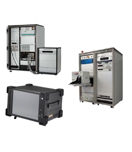
Test systems and simulators
Test System and Simulator includes the control hardware, sensors, and software that collects and analyzes the test results.
Test System and Simulator includes the control hardware, sensors, and software that collects and analyzes the test results.
Our Offerings include Test System and Simulator (TSS), a tailored and Embedded system, which is a computer-controlled equipment that tests electronic devices for functionality and performance.TSS also conducts stress testing with minimal human interaction.TSS includes the control hardware, sensors, and software that collects and analyzes the test results. TSS is considered cost efficient for high-volume testing. Specialization is in developing Custom-made Test Systems, Test Beds as independent Job-Orders or as a part of HSI Testing and Turnkey Testing Projects Delivery.
TSS Test System and Simulator is a vital part of the electronics test scene today. Test System and Simulator enables printed circuit board test, and equipment test to be undertaken very swiftly - far faster than if it were done manually. As time of production staff forms a major element of the overall production cost of an item of electronics equipment, it is necessary to reduce the production times as possible. This can be achieved with the use of TSS, Test System and Simulator.
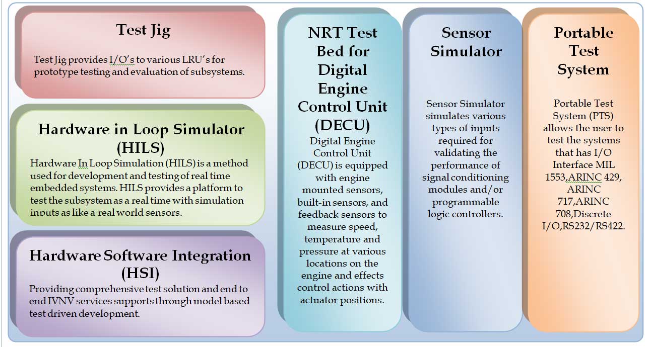
The test jig is provided with repeatable, error free, less human intervention and less time facility. Test Jig is having access to retrieve the measured data of interest as and when required in simpler method. It is capable of identifying the fault and recording the fault as and when it occurs at the time of testing, is adaptable to any type of instruments. The software for controlling and monitoring the real time parameters shall be part of test jig.
The Test Jig will be used to simulate I/O's to varied LRU's for prototype testing and evaluation of avionics sub systems. The Test Jig is envisaged to be of general purpose and reconfigurable in nature for reuse for testing systems at a sub system level. It will also serve as a test platform for maintenance of such Test Jig.
Entire System shall be used a complete Test Plat form operating the entire Avionics Suite and connected to carry out testing of Varied LRU Subsystems through IOs of Discrete, TTL, 1553, RS422 simulated and operated from the built-in Mission Computer.
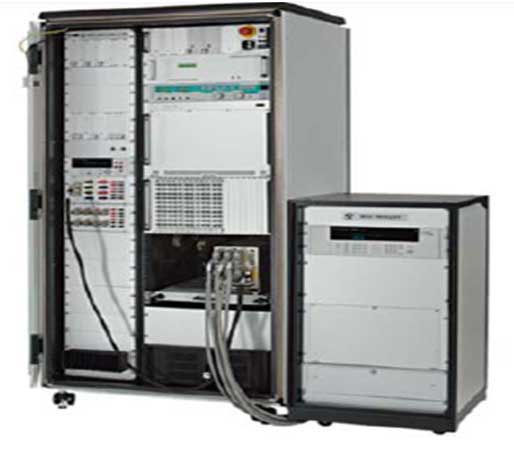
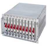
The Test Jig will be a totally integrated in a 19" rack with the varied I/O interfaces terminated at the rear of the enclosure with the necessary cable looms for the testing provided. The simulation Test Jig will have the test application running on Windows and Linux as a dual boot option on the Industrial PC. The supplier has to provide the system as a totally integrated unit with the varied I/O's properly integrated within the Test Jig and with the working and validated test software provided.
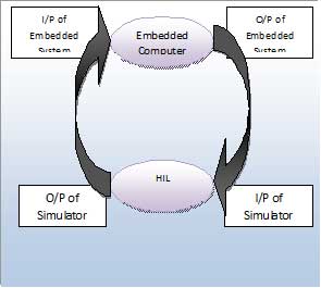
Hardware-in-the-loop (HIL) Simulation is a technique that is used in the development and test of complex real-time embedded systems. HILS may consists of Analog, digitizer, discrete and serial I/O Modules required to simulate real time signals o test the embedded system as a real time operation.
HILS takes input data from embedded system through hardware's like ADC, Discrete serial using software. Acquired data shall be processed using physics modules, algorithms. Output of the processed data shall be converted back to signalsusing DAC, discrete serial I/O modules.
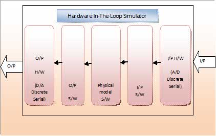
This output signals shall be given back to embedded computers as a real time data to test the functionality o f the system. The embedded system under testing is a bit more sophisticated and there are plenty of systems, after all, in which the output is not simply a function of the present inputs, but is instead a function of the present inputs and some combination of past inputs.
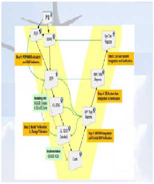
The classical approach to embedded system testing used different testing environments and different test specification techniques on module test, SW integration test, HW/SW integration test and system integration test level.
Typically, the specification used for module and SW integration testing referred to SW functions and Data structure, while the higher integration test level referred to events observable at various system interfaces.
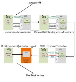
For HW/SW integration testing, we would like to utilize the same abstract machines, but have to take into account that the interface to be accessed on this in integration level is given by an Ethernet-based protocol .
A new IFM accepts the same CSP events from abstract machines. Now the CSP events are transformed into telegrams encoding the key event, and the telegrams are transmitted using TCP/IP.
Many severe errors in control systems are only detected when special sequence of inputs are exercised on the system,
Typically, these sequences occur in real operational situations, but – due to a lack of application expertise are overlooked or taxed as "unrealistic" by the developers and testers involved, so that these situations are neither covered properly in the design nor in the test suites.
A major cause for this problem is given by the sequential programming language style of many test scripting languages, which makes the generation of combinational patterns for input sequences a very tedious and time-consuming task to perform.
NRT Node supports two types of simulations. One is the Virtual Prototype, which simulates a real system in real time for the purpose of evaluating various strategies for the operation of the system. The second is an Environment Model, which simulates the real environment of system under given conditions in order to understand the behavior of the system under test.
The following diagram shows the basic concept of simulation in an NRT system:
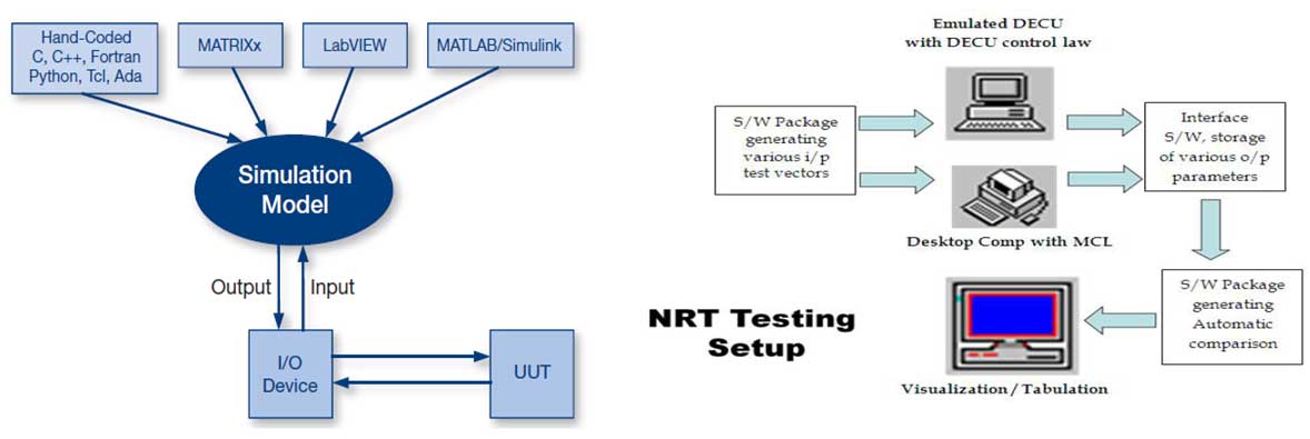
DECU is equipped with communication interfaces to interact with other avionics systems. There are two DECUs (called as DECU lanes) mounted on the engine with one in control and the other in standby. In case of failure of one lane, the other will take control. The major functions of the DECU are
Two DECU lanes with one lane in control and the other in hot standby control the engine. A typical configuration is shown for a Aircraft with dual Engines controlled by each DECU with 2 lanes
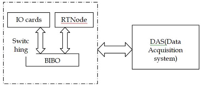
Figure: Overview of sensor simulator
The Sensor Simulator Test Rig simulates various I/O signals like analog voltages, Digital signals, Thermocouple, Pressure/Thrust/Strain gauge etc. to the input of various application cards of the Data Acquisition System.. The Data Acquisition System (DAU) provides the entire instrumented data from the Engine.
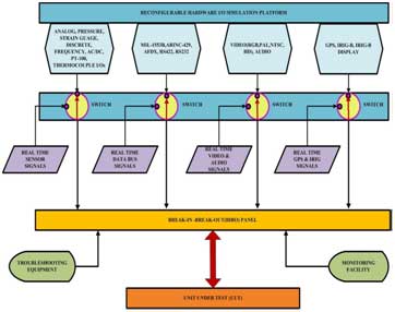
Figure: Overview of Sensor simulator with the BIBO and RT nodes
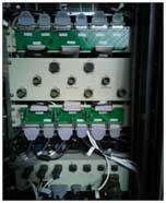
The Sensor Simulator Test Rig is routed over a Break-In-Break-Out(BIBO) Panel for interconnecting all the I/Os and DAU subsystems. The BIBO has to be modular in design and shall be expandable for futuristic needs.
The BIBO has to be connected from various Real world sensors/ simulator outputs and feed the data on to various I/O modules and facilitate for monitoring the simulated as well as to validate data output from the Unit Under Test(UUT).
Switching between Real world sensor inputs and simulator signals from Reconfigurable Hardware platforms to be facilitated in Rig using Industrial Racks.
Hardware platforms to be facilitated in Rig using Industrial Racks. The execution of Real world sensors or simulation platform session will be decided automatically by the user for the Unit Under Test (UUT)
The Sensor Simulator Test Rig is an integrated and scalable software environment and hardware platform for prototyping, development, integration, test and validation of avionics systems. A typical configuration of an Sensor Simulator System is a real-time computing and I/O resources, fault insertion and breakout unit (FIBO), workstations and one or more units under test (UUTs) connected through standard or custom UUT mounts. Additional instruments like DMMs, signal generators or power supplies can be added to the configuration. The control software of an Sensor Simulator system is based on a realtime core which schedules and performs the data exchange between simulations, I/O, data visualization, recording and test executive. Around this core, a set of tools are available for system configuration, session control, simulation integration, data visualization and stimulation, and offline data analysis. A specific set of tools is used for definition, execution and reporting of automatic test procedures.
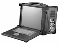
The Portable Test System allows the transmission of messages with high precision timing and reception of messages and events with high resolution and accurate time-tags. Also, all of the device's input and output ports in a system are precisely time correlated.
A powerful embedded recorder allows to record and time-stamp incoming traffic including MIL-1553, ASYNC, ARINC 429 messages and Discrete inputs to the on-board Flash memory. The recorded data can be retrieved trough the Ethernet interface.
The Portable Test System shall consist of a software suite of the following major modules
Portable Test System is an Open Architecture Concept that enables easy maintenance and upgrade to meet any further specific user's requirement
Avionics LRUs have many contact pins that system engineers must access for measurement, insertion, or signal manipulation during development and integration testing. We offer various solutions for Breakout Units with easy and cost-effective signal access.
Breakout Units form factors and housings available in DIN boards for 19″ systems and Customized breakout panels
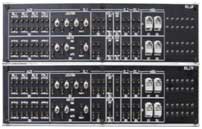
Control Panel acts as measuring points/Input points to ATE/Test Jig for simulating real time inputs.The device uses standard D-sub connectors for all external connections. The maximum current is 6 A per pin. If a separate reference supply is required by the customer a D-sub mixed signal connector (7W2 or similar) is be used for providing up to 40 A per pin. All switches are implemented as «single side stable» to provide fail-safe mechanisms.
Customized Connector Panels are offered part of the test solutions offered. These can be 19" rack mountable or custom formats, that can be used to terminate the I/O from the ATE and connecting it to the Unit Under Test (UUT). Management of high volume signals can be provided through dedicated PCB based interfaces to high density MIL / D38999 Series connectors that matches the UUT connectors.
The wiring shall be provided as per standard / user defined ICD format, including provision for dedicated signal and power connectors.
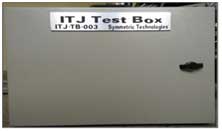
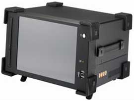
As part of the Integrated Solutions, portable / 19" rack mountable test boxes can be provided, customized to meet the stand alone system test and verification requirements. These can be provided with LED displays, load, test and measurement points.
These can be provided with a complete cable loom kit that can be easily interfaced to the test solution connectors along with an integral test software panel that can be accessed and used by the user for standalone testing and verification of the test solution before connecting to the Unit Under Test (UUT).
Our Comprehensive test software shall have the functionalities as explained below.
The Test System software shall support a uniform data centric communication concept between all data producing or consuming entities in a test session.
The Test System shall support hosting of real time simulation. The number of concurrent simulations shall not be limited by Test System design. The only limitations shall be imposed by physical limitations of computing and network resources of the Test System.
The Test System shall provide a central configuration and control function supporting to perform all configuration and control functions from a single workstation.
The Recording Function shall support high volume real time recording of any data exchanged during a test session:
The Recording Function shall timestamp all data with time stamps. Timestamps shall be synchronized to a single master clock. The recording function shall support streaming mode, i.e. data is continuously recorded after recorder is started until recorder is stopped.
The Replay Function shall support replaying previously recorded data into a test session with the same timing as in the recorded data.
The Replay Function shall support manual and event triggered control (start/stop). The Replay Function shall support replaying data recorded on the Test System. The Replay Function shall support replaying data like flight test data, data recorded from another bench or synthetic (computed) data after corresponding pre-processing.
The Test and Simulation System shall provide a Monitoring Function which supports online monitoring and visualization of any data exchanged during a test session in various views:
The monitoring function shall support viewing data in tabular form The monitoring function shall support viewing data in as X/T graph