FPGA IO Based RT DAS Solutions
Alphi can provide integrated real time data acquisition systems by using the FPGA and I/O modules.
Alphi can provide integrated real time data acquisition systems by using the FPGA and I/O modules.
ALPHI can provide integrated real time data acquisition systems by using the FPGA and I/O modules.
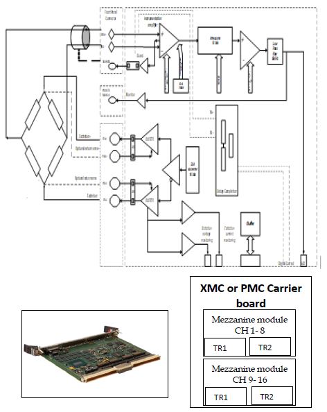
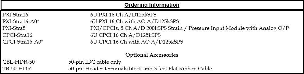
The PXI/CPCIs-Stra16-A0 module offers a complete solution for High Performance data Acquisition applications. Both the A/D and D/A offers 5 us converters. The input instrumentation amplifiers provide differential input buffering, isolation and gain with high CMV capability. A/D operations can be triggered internally (software) or externally through the front panel. Each D/A offers 2 output simultaneously for monitoring and control. A PXI/CPCIs bus connector provides the interface to the host computer with x1 Lane PCI express. The cards are offered in 8/16 Channel configuration with on-board signal conditioning for Strain/Pressure Full/half/Quarter bridge inputs.
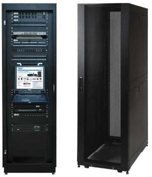
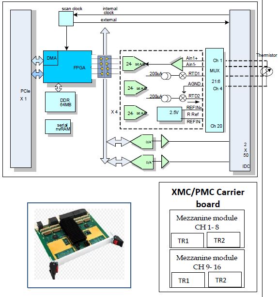
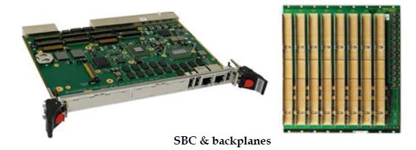
All the modules are pluggable mezzanine modules that can be hosted by any carrier modules based on Bus to suit wide range of application Demands
The PXI/CPCIs-TC/RTD SC module offers a complete solution for Thermocouple Solution. It supports 24 bits precision temperature measurement, with fixed and optional programmable current source. Each of the 16/24-temperature measurement channels has its own A/D converter with two matched 200 μA current sources. The Board also features 16/24 single-ended high impedance analog inputs. Also, a 16-bit A/D converter with 16/24 channels multiplexed allows measurement of input voltage in excess of ± 20 volts.
All the modules are pluggable mezzanine modules that can be hosted by any carrier modules based on Bus to suit wide range of application Demands
The PXI/CPCIs-VOLT SC module offers a complete solution for High Performance Data Acquisition applications. The board has per channel 24-bit A/D 5μs converters. Analog outputs are optional, 5μs D/A converters can be provided per channel. Each D/A offers 2 output simultaneously for monitoring and control. The input instrumentation amplifiers provide differential input buffering and gain (Standard is unity, programmable gain is optional). A/D operations can be triggered internally (Software) or externally through the front panel.
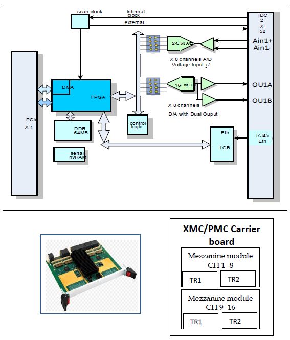
All the modules are pluggable mezzanine modules that can be hosted by any carrier modules based on Bus to suit wide range of application Demands
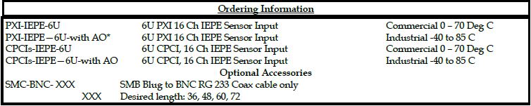
The PXI-IEPE-6U module offers a complete single board IEPE sensor Analog Input. This design is intended for use with a high-end single-channel IEPE sensor interface. A 24-bit conversion at maximum sampling speeds reaching up to 256 KSPS establishes this design at the leading edge of the existing product range. The design targets an input bandwidth of 20 kHZ and a programmable gain between –12 dB to 18 dB. A programmable excitation current of 2 mA to 20 mA as well as a programmable sampling speed down to 32 kSPS means that this design can accommodate different sensor cable distances and different back-end DAQ capabilities. Wire-break and short-circuit detection ensure safe and reliable operation of the sensor interface.
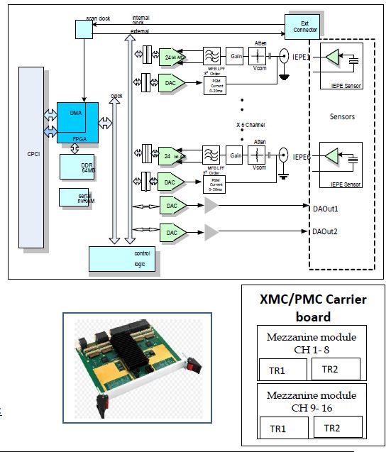
All the modules are pluggable mezzanine modules that can be hosted by any carrier modules based on Bus to suit wide range of application Demands
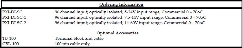
The PXI-DI-SC DAS input board consists of six Zilog Z8536 controllers for DC input control. An FPGA provides the timing and control. Each input has its own optical isolation, and supports a hardware adjustable resistor/optodiode combination for various input voltage ranges. An AMCC PCI controller provides the interface to the host computer. All I/O is accessible from the front panel. Used in industrial applications where there is a need to control devices such as LED’s, lamps, relays, contactors, etc. Full output system isolation is provided up to 2500V/channel.
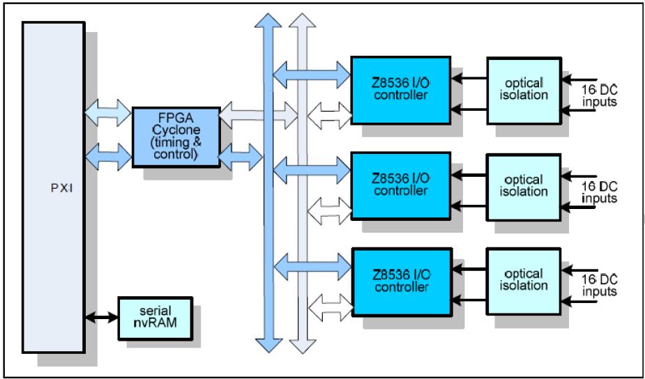
All the modules are pluggable mezzanine modules that can be hosted by any carrier modules based on Bus to suit wide range of application Demands
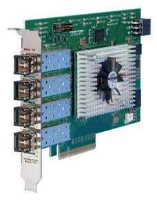
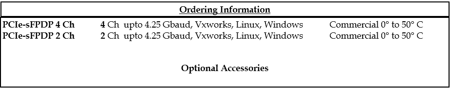
PCIe-sFPDP-4/2 Ch is a member of the Cobalt® family of high performance XMC modules based on the Xilinx Virtex-6 FPGA. A multichannel, gigabit serial interface, it is ideal for interfacing to serial FPDP data converter boards or as a chassis-to-chassis data link. The PCIe-sFPDP-4/2Ch is fully compatible with the VITA 17.1 Serial FPDP specification. Its built-in data transfer features make it a complete turnkey solution. For users who require application-specific functions, the PCIe-sFPDP-4/2Ch serves as a flexible platform for developing and deploying custom FPGA processing IP. In addition to supporting PCI Express as a native interface, the Model PCIe-sFPDP-4/2Ch includes a general purpose connector for application specific I/O.
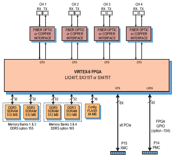
PCIe-sFPDP-4/2 Ch architecture supports up to four independent memory banks of DDR3 SDRAM. Each memory is 512 MB deep and an integral part of the module’s DMA capabilities, providing FIFO memory space for creating DMA packets. In addition to the factory-installed functions, custom user-installed IP within the FPGA can take advantage of the memories for many other purposes
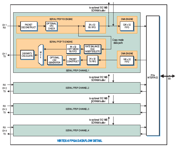
The PCIe-sFPDP-4/2Ch includes an industry standard interface fully compliant with PCI Express Gen. 1 bus specifications. Supporting PCIe links up to x8, the interface includes eight DMA controllers. Each of the four sFPDP channels includes dedicated DMA engines for transmit and receive for efficient transfers to and from the module.
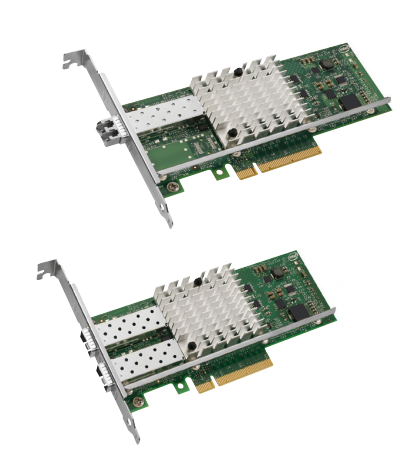
Intel’s family of adapters, the Intel® Ethernet Converged Network Adapter PCIe-10Gig with SFP+ connectivity, are the most flexible and scalable Ethernet adapters for today’s demanding data center environments. Data center networks are being pushed to their limits. The escalating deployments of servers with multi-core processors and demanding applications such as High Performance Computing (HPC), database clusters, and video-on-demand are driving the need for 10 Gbps connections. Customers require flexible and scalable I/O solutions to meet the rigorous requirements of running mission-critical applications in virtualized and unified storage environments.
FCoE encapsulates Fiber Channel frames over standard Ethernet networks, enabling Fiber Channel to take advantage of 10 GbE networks while preserving its native protocol. The PCIe-10Gig adapters offer FCoE hardware acceleration to provide performance comparable to FC HBAs. The adapters support Data Center Bridging, also known as Converged Enhanced Ethernet (CEE), which enables customers to configure traffic classes and priorities to deliver a lossless Ethernet fabric. An Intel Ethernet Converged Network Adapter PCIe-10Gig reduces TCO by eliminating redundant fabrics and saves the cost of expensive FC HBAs and FC switch ports.
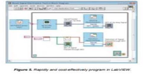
The lab view Run-Time Platform from Lab VIEW-built applications relates to the concept of componentbased software development and distribution. The world of software today is a component-based world. No longer do we develop and deploy monolithic applications. Rather, we develop software that reuses common components as often as possible. When we deploy this software, more than a single file is almost always required. Applications that use the same components are then able to use the same common files, resulting in smaller disk usage than if each application included all required components. Perhaps even more importantly, developing component-based software allows us to update individual components separately from the software that uses those components.
The principal complaints about Lab VIEW applications were their large size. A contributing factor to the size of Lab VIEW applications was that the Application Builder includes a copy of the Lab VIEW Run-Time Engine in every application. Using the principles of component-based software, one way to solve this problem was to separate out the common component, the Lab VIEW Run-Time Engine, so that all Lab VIEW-built applications on a system could use the component.
Many of the technologies that we use in Lab VIEW today are available only as components. Examples include Data Socket, NI-Reports, and the Mesa graphics library for displaying three-dimensional controls and indicators.
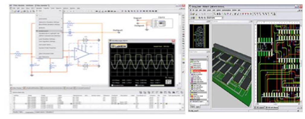
Lab view development environment With the Lab VIEW Embedded Model for Black fin Processors, domain experts can develop their applications from algorithm design and prototyping to deployment and test – all using one platform. The graphical software includes more than 140 Black fin-specific, hand-optimized math, analysis, and signal processing functions
Integrated I/O such as audio and video DACs, ADCs and CODECs; and on-chip debugging, as well as easy graphical interconnection via Ethernet. The Lab VIEW Embedded Model for Black fin Processors includes the fully featured and accessible ADI Visual DSP++ C development and debugging environment for low-level access and real-time, interactive debugging and deployment directly to Black fin. Engineers and scientists can debug code graphically in Lab VIEW or simultaneously debug both the graphical code and generated C source code. The new model is shipped with examples for applications including audio, control, power monitoring, and communications. It also provides easy connectivity to the extensive range of NI test and measurement hardware for deploying external simulation and test methodologies early in the development process.