Robotic Process Automation and AI Technology
Robotic process automation (or RPA) is a form of business process automation technology based on metaphorical software robots (bots) or artificial intelligence (AI) workers.
Robotic process automation (or RPA) is a form of business process automation technology based on metaphorical software robots (bots) or artificial intelligence (AI) workers.
Robotic process automation (or RPA) is a form of business process automation technology based on metaphorical software robots (bots) or artificial intelligence (AI) workers.
Robotic Process Automation is the technology that allows anyone today to configure computer software, or a “robot” to emulate and integrate the actions of a human interacting within digital systems to execute a business process. RPA robots utilize the user interface to capture data and manipulate applications just like humans do. They interpret, trigger responses and communicate with other systems in order to perform on a vast variety of repetitive tasks. Only substantially better: an RPA software robot never sleeps and makes zero mistakes.
Artificial Intelligence (AI) is combination of technology and cognitive intelligence for simulation, processing of information and knowledge to build capability in a machine to imitate human behaviour. It is a transformative technology that has tremendous applications in the social, economic and military fields. Till some time back we had robots operated by a human or through a set of programming to perform repetitive task. The technology is already present in many sectors of economy, such as mapping technologies, hand writing recognition for mail delivery, financial trading, surveillance, target acquisition, smart vehicles, ammunition, and robots performing numerous industrial, medical and military tasks.
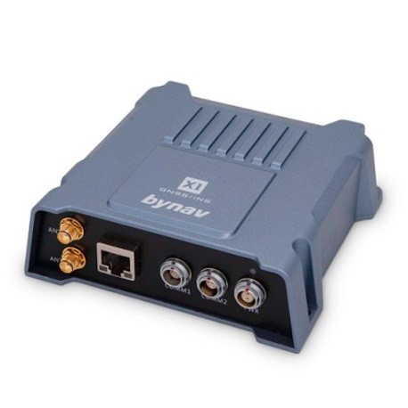
Highly integrated GNSS/INS high-precision navigation system that adopts the absolute accuracy of GNSS positioning and the stability of Inertial Measurement Unit (IMU) gyro and accelerometer measurements are tightly coupled to provide real-time navigation results such as centimeter position, velocity, and 3D attitude etc.
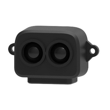
TF-Luna is a single-point ranging LiDAR, based on the TOF principle. With unique optical and electrical design, it can achieve stable, accurate and highly sensitive range measurement. Solid State 3D LIDAR Wide FOV LiDAR Sensor is a solid-state infrared LiDAR which is developed based on the ToF principle. Equipped with its special hardware design, it could complete the measurement of wide horizontal FOV and output the grey and depth information at the same time.
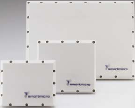
The Universal Medium Range Radar (UMRR) sensor family measures positions and speed of multiple targets simultaneously with high accuracy and short measurement cycles. The sensor platform is flexible and works under adverse weather or light conditions. The sensors operate in the 24 GHz ISM band and have been certified worldwide. Software parameters, bandwidths, or antenna patterns can be optimized for use in multiple sensor applications.
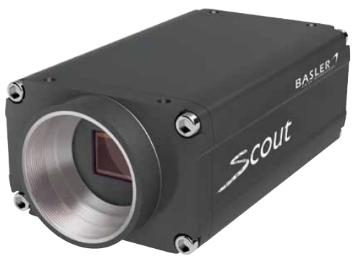
The Basler scout family is based on a selection of the best Sony CCD sensors and offers a wide variety of resolutions and speeds. The family also includes a high-performance CMOS sensor from Micron. With their new Gigabit Ethernet (GigE) and FireWire-b™ (IEEE 1394b) interface technologies, the cameras in this family are defined by state of the art technology that lets you get the maximum performance from each sensor.
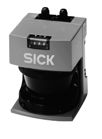
Our non-contact Laser Measurement System (LMS) can be used for standard applications involving measurement of objects and position determination, monitoring areas, vehicle guidance and collision control. The fundamental ability of LMS is to offer accurate distance measurement throughout the 180° scanning field. Within this field, the LMS can be programmed to monitor multiple zones. These zones can then be assigned to solid state outputs of the LMS. Beyond this simple mode of operation the LMS will transmit all 180 measurements via a high speed RS 422 serial port. The Host system can then use this data for specific applications.
LMS measurements are based on time of- flight measurement. The LMS calculates the distance to the object using the time of flight of pulsed light; i.e. the length of time between sending and receiving the beam of light.
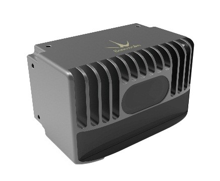
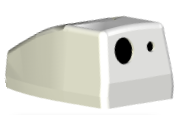
Fuzor enhances situational awareness for pilots in darkness, smoke, haze, rain, fog and other hazardous situations. It is a multi-band fusion system consisting of two line replaceable units mounted on ground or aerial vehicles. Extended dynamic range and depth of field enhance the clarity and precision of the image while highlighting details that would typically not be visible to the naked eye. The sensor package consists of a Long Wave IR camera and a combination of Electro Optical (EO)/Short Wave IR SWIR (optional) imagers. The LWIR senses radiation in the 7.5–14 µm bands. It can image background scenery, terrain features and obstacles at night and in other low visibility conditions. The processing unit is a ruggedized platform equipped with intelligent software that fuses imagery from the multi-band sensors into one common easy to interpret video feed.
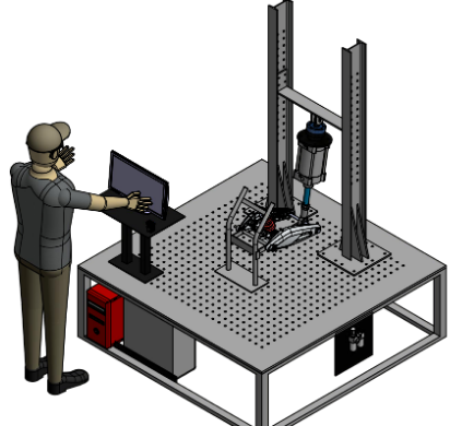
We design & manufacture customized laboratory & production testing systems -
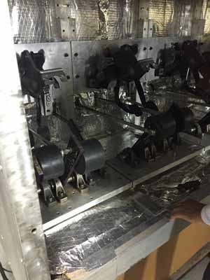
These are extremely robust testing machines developed in house by Task for a variety of applications as demanded by the industry. They can range from fatigue testing to structural testing to robotic testing for Electro-mechanical components such as automotive switches, electronic testing machines with a completely automated computerized interface which generates reports and readings as per the requirement of the user.
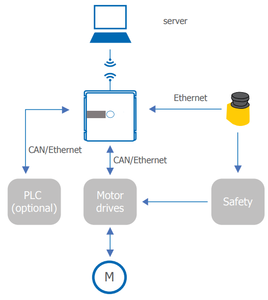
Autonomous navigation system it provides an autonomous ‘natural feature navigation’ system for compact vehicles, calculating its position, driving the vehicle, interfacing with the vehicle’s safety sensors and handling mission management (i.e. start here, go there, wait for the door to be opened etc.).
The product provides the most standard and reliable interfaces combined with a set of I/Os to enable the automation of typical forklifts and AGVs.
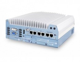
Nuvo-7164GC is a rugged edge AI inference platform designed for advanced inference acceleration applications such as voice, video, image and recommendation services. It supports NVIDIA Tesla P4 GPU, featuring 5.5 TFLOPS in FP32 and Tesla T4 GPU, featuring 8.1 TFLOPS in FP32 and 130 TOPs in INT8 for real-time inference based on trained neural network model. In addition, it supports Intel 9th/ 8th-Gen Coffee Lake Core 8/ 6-core CPU and 32 GB DDR4-2666, offering great balance between CPU, GPU and memory performance.
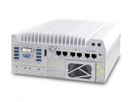
Nuvo-7000 series includes Neousys' track-proven technologies for superior ruggedness and versatility, such as effective fanless design, patented expansion Cassette and proprietary MezIO interface. It also incorporates cutting-edge computer I/O like USB 3.1 Gen2 with up to 10 Gbps throughput and M.2 2280 M key socket for NVMe SSD or Intel Optane memory for ultimate system performance. The plethora of on-board I/O ports (GbE, USB and COM) feature sophisticated protection circuits to endure stress from ESD and power surge. This makes Nuvo-7000 series by far the most rugged embedded computer we've ever created.
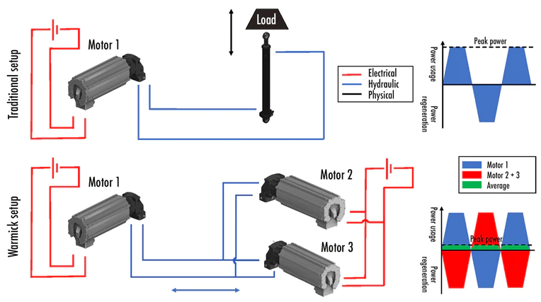
In many robotic systems, actuators are often required to operate in distinctively different torque-speed load conditions. Machine tools, for instance, are usually either moving at high speed unloaded during reaching phases, or moving slowly applying large forces during manufacturing operations. Also, a legged robot, for example, has to move its leg forward quickly through the air and, once touching the ground, it has to bear a large load, or a gripper needs to reach the part quickly and then has to apply large holding forces.
To meet the power requirement of all operating points with small actuators, it is proposed to use electric motors coupled to a gearbox where the reduction ratio can be drastically changed online. Using such Variable Gear-ratio Actuator (VGA) on the many joint of robotic systems, leads to offering a wide range of properties in terms of speed, force and impedance.
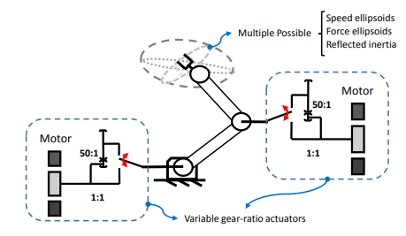
An actuation technology, consisting of a mechanical architecture called DSDM (dual-motor dual-speed) used in conjunction with novel gear shifting control algorithms, that make possible fast and seamless transitions between two radically different gear-ratios. The below figure illustrates a DSDM actuator prototype.
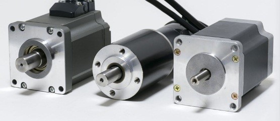
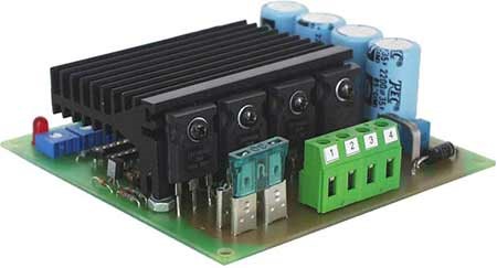
A motor controller is a device or group of devices that can coordinate in a predetermined manner the performance of an electric motor. A motor controller might include a manual or automatic means for starting and stopping the motor, selecting forward or reverse rotation, selecting and regulating the speed, regulating or limiting the torque, and protecting against overloads and electrical faults.
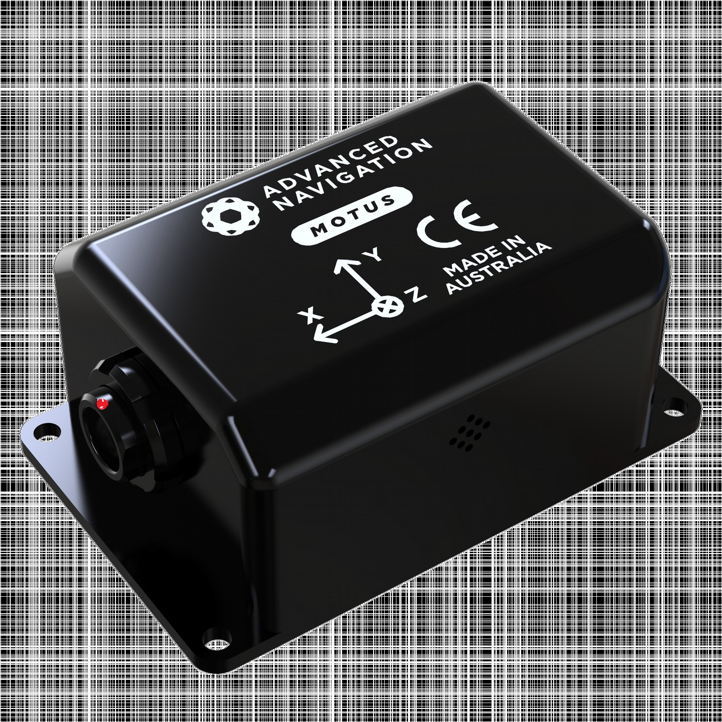
Motus is a miniature ultra-high accuracy MEMS IMU. It features some of the highest accuracy MEMS accelerometers and gyroscopes currently available combined with magnetometers. Motus is fully calibrated for all sensor errors over a wide temperature range and can be software upgraded to AHRS or INS functionality. It is available in both OEM and enclosed packages.
The Motus Manager software is downloadable from the software tab of the Motus page on the Advanced Navigation website. It allows Motus to be easily configured and tested. Motus can provide amazing results but it does need to be set up properly and operated with an awareness of its limitations. Please read through this manual carefully to ensure success within your application.
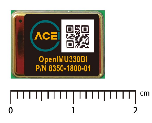
The OpenIMU330BI module integrates highly-reliable MEMS inertial sensors (acceleration, angular rate/gyro) in a miniature factory-calibrated package to provide consistent performance through the extreme operating environments.
It is easy to synchronize and interface with external GPS, as well as other sensors. The main feature of OpenIMU300BI is triple redundancy for each inertial sensor.
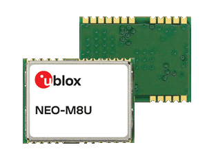
The NEO-M8U module introduces u-blox’s untethered dead reckoning (UDR) technology, which provides continuous navigation without requiring speed information from the vehicle. This innovative technology brings the benefits of dead reckoning to installations previously restricted to using GNSS alone, and significantly reduces the cost of installation for after-market dead reckoning applications.
The strength of UDR is particularly apparent under poor signal conditions, where it brings continuous positioning in urban environments, even to devices with antennas installed within the vehicle. Useful positioning performance is also available during complete signal loss, for example in parking garages and short tunnels. With UDR, positioning starts as soon as power is applied to the module, before the first GNSS fix is available.
Uninterrupted positioning under all signal conditions using a built-in sensor without need for an electrical connection to the car.
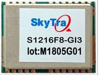
The S1216F8‐GI3 is a satellite navigation receiver capable of using L5 NavIC and L1 GPS / GAGAN / GLONASS signal to provide 3D navigation in a single compact SMD module. The S1216F8‐GI3 has 56 tracking channels and could track all in‐view satellites. It is fully autonomous such that once power is applied, the receiver automatically searches, acquires and tracks satellite signals. When a sufficient number of satellites are tracked with valid measurements, the receiver produces 3D position and velocity outputs.
NavIC + GPS + GLONASS triple‐satellite capability enables using greater number of satellite signal than GPS‐only receivers. The increased satellite number offers superior performance in challenging urban canyon and multipath environments.
The S1216F8‐GI3 module contains SkyTraq Venus 8 positioning engine inside, featuring high sensitivity, low power consumption, and fast TTFF. The superior cold start sensitivity allows it to acquire, track, and get position fix autonomously in difficult weak signal environment. The receiver’s superior tracking sensitivity allows continuous position coverage in nearly all outdoor application environments.
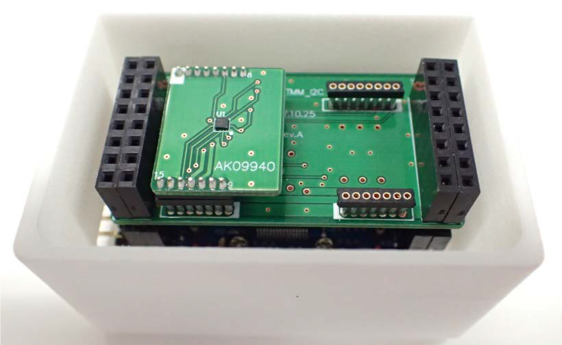
AK09940 is ultrahigh precision 3-axis electronic magnetometer IC with ultrahigh sensitive TMR sensor technology. Small package of AK09940 incorporates magnetic sensors for detecting magnetic field in the X-axis, Y-axis, and Z-axis, a sensor driving circuit, signal amplifier chain, and an arithmetic circuit for processing the signal from each sensor. Self-test function is also incorporated.
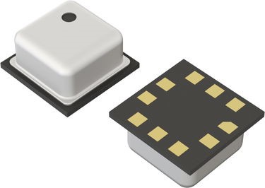
BM1386GLV is piezo-resistive pressure sensor. BM1386GLV performs temperature compensation for MEMS inside chip internally, so it’s very easy to get pressure information.
This 1/3-inch format, 1.2 MP imaging device has been designed to address the challenging requirements of automotive in-cabin cameras. The new global shutter sensor allows the camera to “freeze” fast moving scene data, and ensures effective synchronization with pulsed light sources. The AR0135 sensor incorporates a new innovative global shutter pixel design, with 10X lower dark current and 4X higher shutter efficiency vs. previous generation products. These improvements allow the sensor to produce clear, low-noise images, in both low-light and bright scenes, and in high temperature environments. This performance enables the required eye tracking and gesture detection functionality in next generation automotive in-cabin systems.
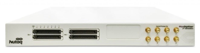
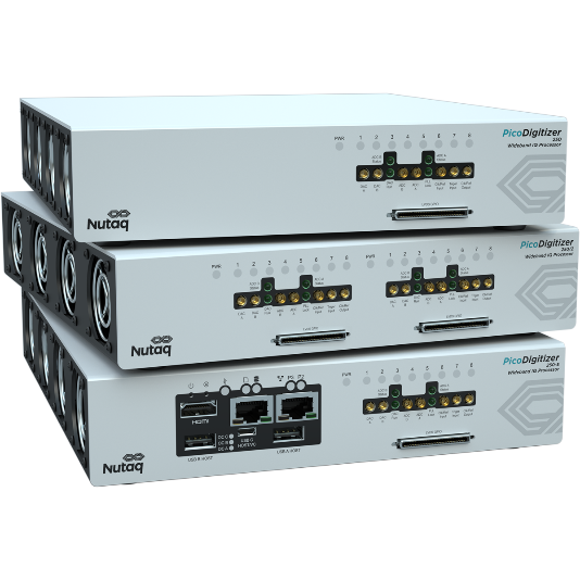
The PicoDigitizer 125-Series and MI250 Series is a high channel density, phase coherent, FPGA-based table top DAQ solution. It incorporates up to 64 channels on a Virtex-6 FPGA, sampling at 125 MSPS, and offers an embedded version which includes an Intel Quad-Core i7 processor for standalone applications. Additionally, signal generator outputs (DACs) can be added to the system for combined multichannel acquisition & transmission processing.
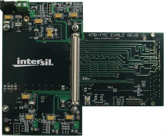
Renesas offers two options for evaluating high-speed analog-to-digital converter products with LVDS and/or LVCMOS outputs. A complete, turnkey evaluation platform is available, which includes data capture hardware and software to process and display acquired data. This system provides the fastest and easiest path to evaluating an ADC since no additional software coding is required of the user.
The second option is an adapter board that facilitates connection of an ADC daughter card to an FMC-based FPGA development board. This solution offers greater flexibility since the user has full access to the FPGA functionality and can therefore perform signal processing operations and/or "hardware in the loop" simulations. No software is provided for this option since there are a wide variety of supported FGPA development boards.
Nutaq’s software development tools are a comprehensive suite that includes:
that significantly reduce the time customers spend on low value-added tasks such as programming interfaces, adjusting FPGA constraints, debugging Host drivers, etc.
Nutaq’s development framework also features seamsless integration to model-based design tools (such as Simulink and GNU Radio), combining a graphical development environment and automatic code generation. These tools greatly accelerate the development of applications, shorten the development cycle and reduce project costs.
Nutaq’s software tools are designed to enable and facilitate migrating from our standard products to a modified, customized or even miniaturized versions of them (For Nutaq customized hardware services, please click here). Built for embedded applications, Nutaq provides complete support for Linux and Windows environments on x86 processor architecture.
Combined with Nutaq FPGA-based standard systems, Nutaq development software tools provide a complete Turnkey System for developing and deploying next generations embedded real-time computing and algorithms acceleration (HPC) systems, mainly targeted for the following applications:
Depending on Nutaq systems and options, software development tools are provided with three different levels of integration, as the following:
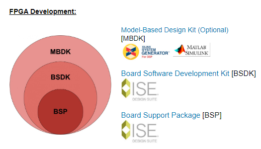
The Nutaq Board Software Development Kit (BSDK) is a complete set of tools that includes IP cores, Frameworks, APIs, easy-to-use GUIs and application examples that significantly reduce the time customers spend on low value-added tasks such as programming interfaces, adjusting FPGA constraints, debugging Host drivers, etc.
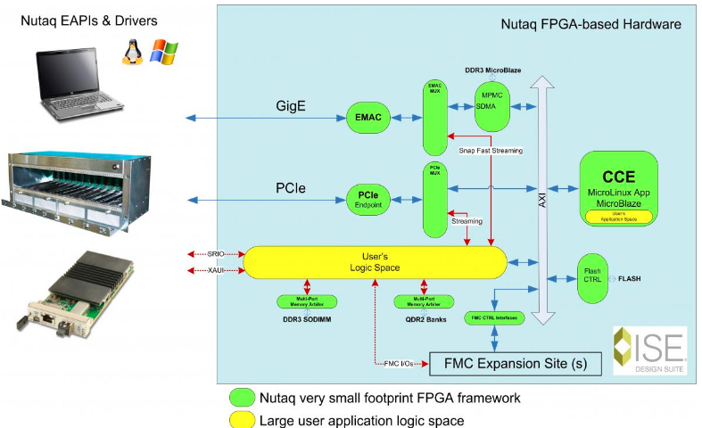
A MicroBlaze processor instantiated within the FPGA fabric, running a commercial, embedded Linux distribution. This fabric risk processor runs Nutaq CCE application and may also run user-defined task/application.
The CCE handles the bootloader, the start-up sequence, the TCP-IP and PCIe communication and configuration commands, etc. This software component is the board interface with the host Command Line Interpreter, GUIs or any other software running on a remote PC intended to communicate with the Nutaq FPGA-based hardware. The CCE is an implementation of a RPC (Remote Procedure Call library). It exposes the function of the Nutaq Software Libraries to the network. The CCE receives and handles TCP (GigE) or PCIe commands, answers to request coming in real-time and supports multi-user connections. For high efficiency and easy cross-platform API supports, a simple protocol is used. Basically, requests contain a function id and a parameter list. Each function from the Nutaq Software Libraries possesses a unique id. When receiving a request, the CCE call the corresponding function using a function lookup table.
The Extended Application Programming Interface (EAPI) can run on either a Windows or Linux operating system.
This EAPI enables host-based applications to remotely control Nutaq’s FPGA boards, via the Central Communication Engine, through an Ethernet connection with a TCP transport (Windows or Linux) or PCIe interface (Linux only).
The command-line interface (or CLI) is the basic client interface for Nutaq FPGA boards. It consists of a shell where one can type commands, interacting with the board’s FPGA. The CLI offers many useful features like programming an FPGA bitstream in the onboard flash memory, reading or writing specific addresses on the AXI bus, loading data at some specific address in DDR3 SDRAM, using RTDex, etc. The CLI is a Python script file, which means that it dynamically parses and runs commands. It is also possible to write series of commands in text files and have these run as if they were typed in directly at the command prompt.
Nutaq RTDEx IP core main objective is to provide customer a framework to exchange data with a host device through the GbE or PCIe links with the highest bandwidth and lower latency possible. On both interfaces, Nutaq CCE is used to configure DMA engines and registers to initiate data transfer. In order to avoid any bottleneck in the data throughput, the MicroBlaze processor is bypassed during data packet transmission allowing the full data bandwidth and lower latency.
The FPGA SDRAM recording module enables storing bursts of data in the onboard SDRAM. These can then be transferred to a host device for storage and analysis. The FPGA SDRAM playback module enables transmission of large portions of data from a host device such as a computer to the FPGA SDRAM these can then be read by the FPGA at high speed. Nutaq recording and playback FPGA core is equipped with a four-port memory controller core to permit it to sequentially access the DDR3 SDRAM. The core makes it possible to store data in memory from an FPGA input, for example. Similarly, it makes it possible to read data from the memory, and then send it to an FPGA output channel. The core also has two ports that can be connected to the RTDEx core, allowing a host device to read data from or write data in the FPGA SDRAM memory concurrently.
The FPGA QDR Read and Write core enables easy user access to such high speed and low latency memory.
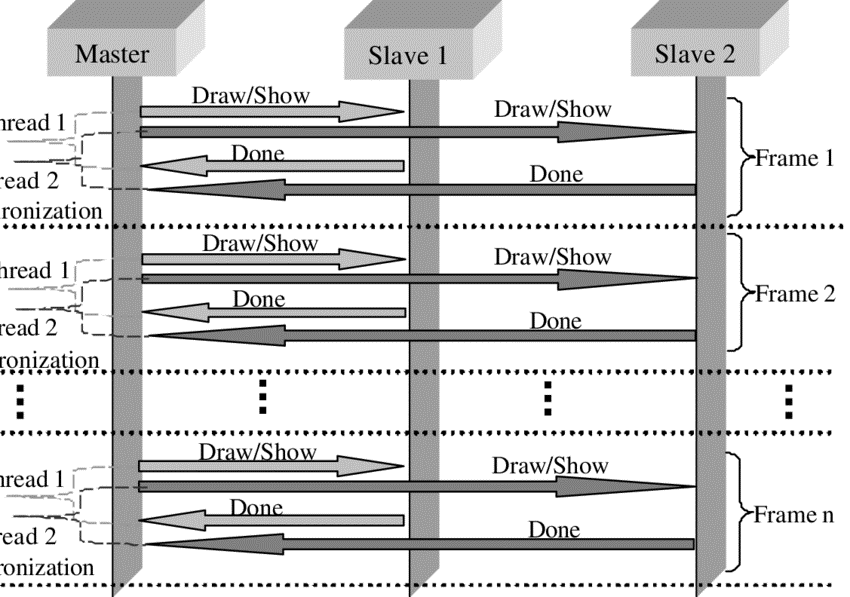
In a multithread system, synchronization is extremely important in a memory system — the key hardware capability is an uninterruptible instruction or instruction sequence capable of atomically retrieving and changing a value.
Basic problem: If two concurrent threads are accessing a shared variable, and that variable is read/modified/written by those threads, then access to the variable must be controlled to avoid erroneous behavior. Once a hardware synchronization mechanism exists, software synchronization mechanisms are then constructed using the capability. “Locks” are used to create “mutual exclusion” and to implement more complex synchronization mechanisms.
Timestamps are important for keeping records of when information is being exchanged or created or deleted online. In many cases, these records are simply useful for us to know about. But in some cases, a timestamp is more valuable.
This is where ‘trusted’ timestamping comes in. These types of timestamps are generated by a trusted third party using secure FIPS-compliant hardware, so they are not subject to manipulation by a local user. Trusted timestamping means that you can say with a high level of certainty that the date on the timestamp is accurate and hasn’t been tampered with.
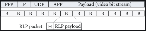
Multimedia streaming is becoming increasingly popular. The multimedia standard MPEG-4 was designed to support scenes of different levels of complexity and applications with low bandwidth up to very high bandwidth requirements. Scalable video encoding is supported as well. This allows MPEG-4 streaming software to adapt video quality dynamically in the network to currently given QoS conditions. We evaluate packetization modes designed to transport MPEG-4 elementary streams over RTP connections, based on an implementation of an MPEG-4 video server and a demo client. Suitability of the packetization modes for video stream adaptation in the network nodes is discussed.
The client-server pair uses appropriate protocols like RTP/ RTCP to measure network QoS parameters. Using these measurements, the server adjusts the transmission band- width. Consequently the perceived video quality on the client side varies over time, especially sudden or frequent video quality changes are possible. This method is called non-transparent video scaling as it involves both client and server. The second method shifts the video adaptation task from the server into the network because the network routers have timely knowledge about current QoS situations. This is called transparent video scaling because it does not involve the end nodes in the quality adaptation process.
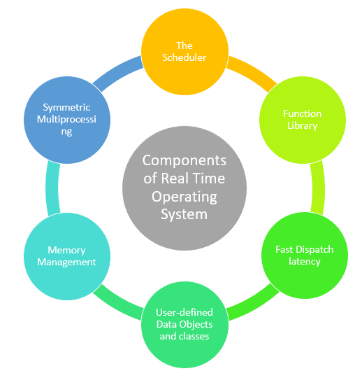
Real-time operating system (RTOS) is an operating system intended to serve real time application that process data as it comes in, mostly without buffer delay. The full form of RTOS is Real time operating system.
In a RTOS, Processing time requirement are calculated in tenths of second’s increments of time. It is time-bound system that can be defined as fixed time constraints. In this type of system, processing must be done inside the specified constraints. Otherwise, the system will fail.